So I’ve been trying to wrap my head around how this AB class amplifier designed by a brilliant and entertaining YouTuber, Mehdi Sadaghdar. I follow his YouTube channel and highly recommend that you do to if you’re even remotely interested in circuits or enjoy watching entertaining and informative videos, totally do it.
I’ve been brushing up on circuits and found his video and page on building an audio amplifier to drive a large speaker. You use amplifiers every day from inside your phone to jammin’ on your guitar or even in your microwave.
The reason you want to build an amplifier is to take a really small signal, like one for your phone, and use it to power a large speaker like for an entertainment system. You couldn’t just directly hook up your phone to the speaker, your phone doesn’t have enough power to do so, hence the amplifier. He designed this circuit which you can see by visiting his page I linked above, but I recreated his circuit in PSpice which is a circuit simulator.
I don’t have any fancy oscilloscopes or the plethora of parts to build it, so I’m going to have to do with a sim for now.
This is the circuit I came up with in PSpice, the parts aren’t exactly the same as defined in his article, but it’s close enough.
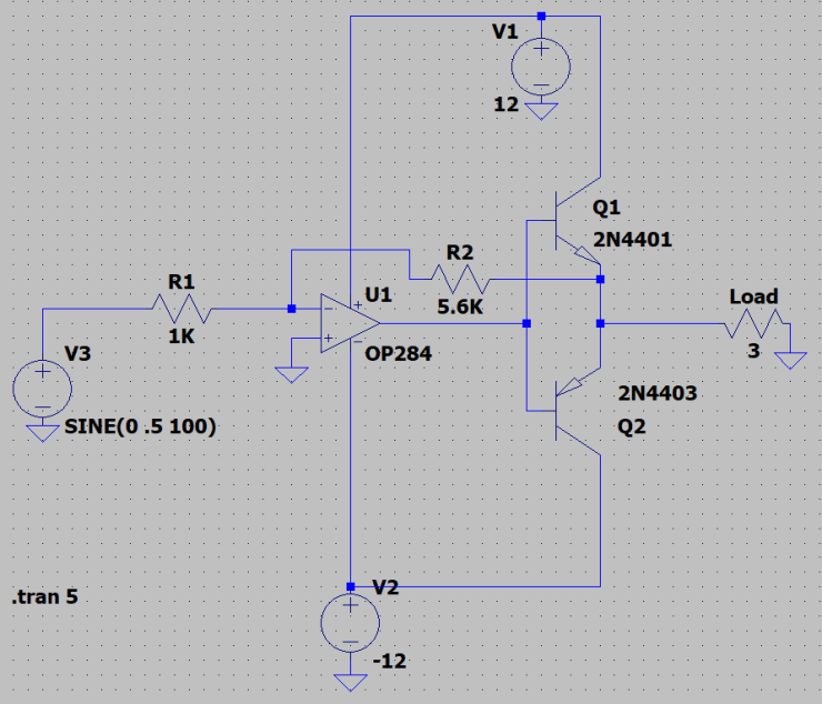
The circuit takes any input, shown by V3 as an input Sine wave with 0.5 V amplitude and 100 Hz frequency, passes it through an inverting opamp (flips the incoming signal and amplifies it by the magnitude of the ratio of R2/R1). The reason why we have R2 feeding back into the opamp is to limit the gain of the signal. Theoretically, an opamp has infinite gain, but that’s really not feasible in a realistic circuit with finite values, so we stick with a gain of about 5.6 times the original input signal.
It then feeds into the two transistors an NPN and a PNP configuration at the end which is called a push-pull. If you’re unfamiliar with transistors, know that they act like valves so they can pass through a large amount of current that is proportional to the base current. This current is what is needed to drive the larger speakers and are provided by the positive and negative voltage sources on the top and bottom of the drawing instead of your itty bitty phone.
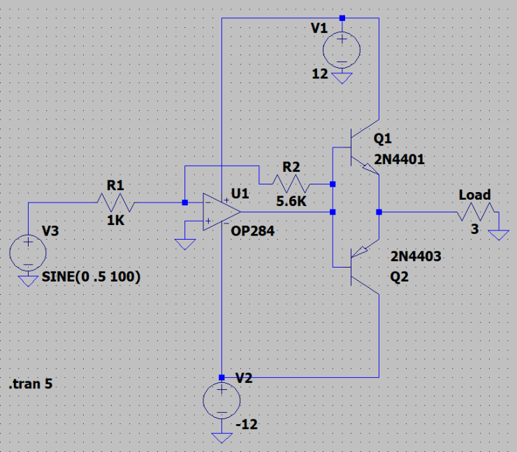
What I didn’t understand initially was why R2 which is called the feedback resistor was connected to the output of the transistors and not directly to the output of the opamp which I always see in my textbooks. So, I set up a separate circuit and changed where R2 was connected:
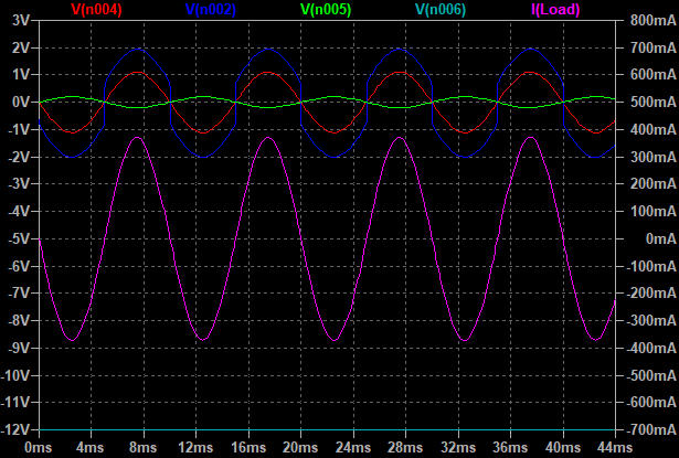
I then ran some various simulations which allowed me to virtually probe (use an oscilloscope for all of you more dirty-minded individuals) to look at the voltages at the different points in the circuit. Here’s what I found out and what Mehdi tried to explain, but I didn’t really understand it until I started to actually do the circuit building. Another reason to practice problems in real life instead of just reading a text. This is what the output it looks like with the original layout:
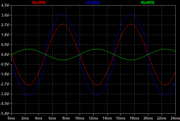
The green trace is the input signal with 0.5 volt amplitude input, the blue is the inverted output at the far right end of the circuit. Notice it is 5.6 times the input voltage due to the opamp or just about a 2.8 V amplitude. The red matches the shape of the green and is smooth. The odd one out is the blue waveform with nearly vertical shifts but that’s not driving the speaker so it’s okay.
Now, the modified circuit output:
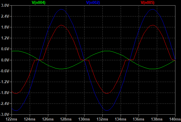
You still have the green trace as the input, the blue as what is seen at where R2 is now connected to the output of the opamp, but now the red output signal (which goes to the speaker) is not a properly magnified and inverted version of the green input signal, it has odd flat parts which are called “clipping” and are a form of signal distortion.
If you’re using my super crappy modified amplifier for let’s say your guitar, you’re gonna get some crappy sound. Even worse, if you look at the current through the speaker it’s gonna cause some odd crappy sound from your speakers.
So what’s the difference and what understanding did I come to by manually making this circuit and playing around with it?
Here’s where the crazy blue line comes in, transistors usually take about 0.6 to 0.7 volts of input to turn on or off, this is their forward breakover voltage. So when the voltage is low, the push-pull transistors never transition into their “on” state and you get a waveform that isn’t a correct representation of the input. In fact, the speakers won’t even turn on properly since the current won’t be flowing through the transistor. When you connect the feedback loop to the output of the transistors and the transistors aren’t on, there is no negative feedback going back to the opamp input to limit the gain, so the gain spikes extremely quickly until it reaches the threshold voltage of the transistor and it conducts properly and operates in forward bias, the base current is linearly magnified and everything is happy as in the first waveform picture.
In my modified version, the opamp always sends negative feedback to the input and so it keeps the signal low and doesn’t allow for the super fast scaling of the signal into the push-pull transistors. So the current doesn’t even flow to the speaker for the portions of the cycle which are less than 0.7 volts in magnitude. Hence the clipping. It gets even worse if your input signal is lower, causing more of the signal to be clipped by the transistor cutoff.
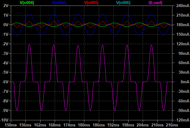
In this freak of nature graph, the original green signal is not even close be being represented properly by the red output signal. The hot-pink current through the speaker is hot-sh*t because that’ll make it have awful sound.
Reattaching the feedback loop to the transistor emitters gives the proper recreated voltage and current curves:
Now, this is only at about 100 Hz. If you are considering audio for human ears, that goes anywhere from 20 Hz to 20,000 Hz. Unless you’re really old, then your hearing decreases in sensitivity to below ~18,000 Hz and then you die. Just kidding, you don’t need to be that old to lose your hearing at higher frequencies.
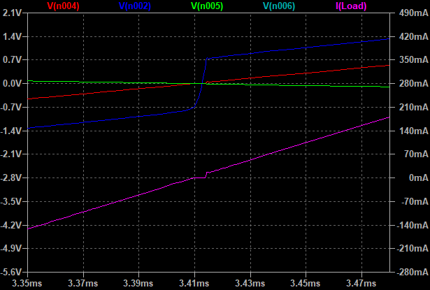
Running the simulation at higher frequencies, you start seeing some artifacts in the waveform, here it is, zoomed in, at 440Hz, a nice pleasing A note.
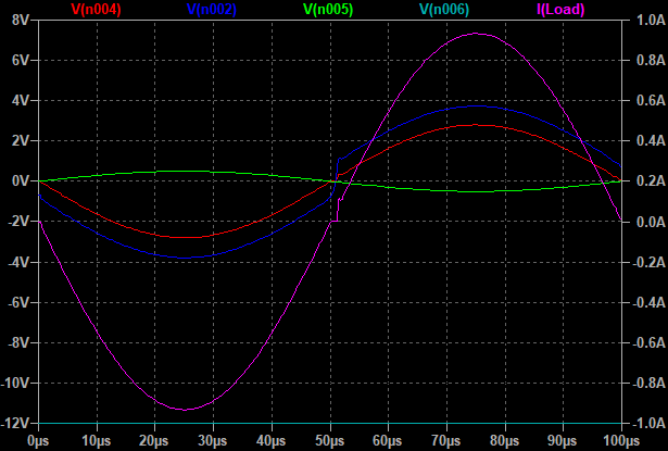
And here is an even larger artifact at a skull-splitting, ear-bleeding 10,000 Hz, a note that makes you want to jump off a building.
These type of artifacts are what make some cheaper amplifiers give “bad” sound as they might not accurately give a pure sinusoidal soundwave that might be produced by pickups on your sweet banjo. Usually, cheaper quality amplifiers have cheaper transistors and opamps that don’t switch as quickly as more expensively made ones and make these type of artifacts even worse.
Apparently, some audio snobs only want to use vacuum-tube based amplification attached to their super hi-fi vinyl record player because it sounds better. I guess. But then again I don’t like spending 20 dollars for two pieces of avocado toast.
SO WHAT DID I LEARN!?
- Remember that transistors always have a forward bias which you must overcome for them to turn on and you must arrange your circuit accordingly in order to overcome that bias properly to avoid signal clipping.
- All electronics have boundaries. Nearly every piece of hardware you use today is specially made to handle a certain range of frequencies. The driver created by Mhedi and simulated by me would be perfectly fine for a subwoofer (which is what he designed it for), frequencies ranging from 20 Hz to the low 100’s of Hz. Higher frequencies would require different hardware to avoid signal artifacts.
- Build what you study! Don’t just sit there passively and think you understand how dozens if not hundreds of pieces of knowledge come together in a real-life application. Work your brain out with both studying and building/testing. By failing to see how something worked and actually building it (sort of), I learned a hundred times more things than just nodding and thinking I got it.
Keep on learning, everybody!
