Okay, so there’s some rapid-fire learning going on here. In the few hours since my last post, I’ve googled, coded, and tested my way to a good spot!
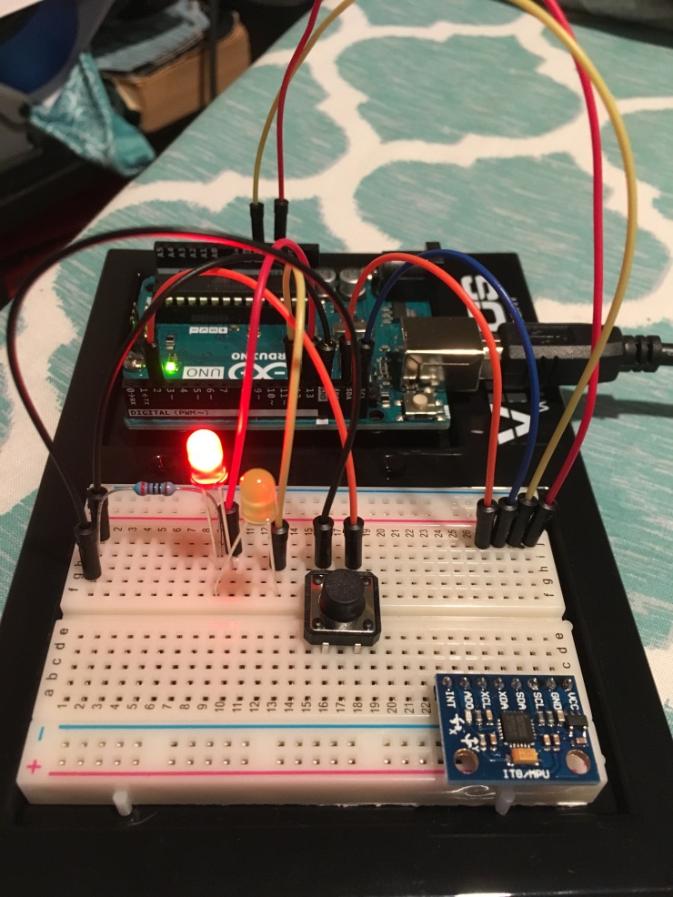
First, I extended my small circuit to include a second LED that would light up for a predetermined amount of time if a button was pushed. I piggybacked the “GO” LED on the “STOP” LED’s resistor without any issue since they wouldn’t be on at the same time I didn’t need to worry about excess current through the resistor during normal operation.
The following is the code that I found and modified for my purposes. It originally did not have a delay but just turned on when the button was pushed down. Now, the button operates as a toggle and a timer keeps the light on for whatever length of time defined by the “interval” variable. (This is all written in C++ for those of you wondering why it doesn’t look like my beloved Python.)
// constants won't change. They're used here to set pin numbers:
const int buttonPin = 2; // the number of the pushbutton pin
const int STOPPin = 13; // the number of the STOP LED pin
const int GOPin = 12; // the number of the GO LED pin
const long interval = 10000; // interval for how long the loop will run in miliseconds

// variables will change:
int buttonState = 0; // variable for reading the pushbutton status

void setup() {
   // initialize the LED pins as an output:
   pinMode(GOPin, OUTPUT);
   pinMode(STOPPin, OUTPUT);
   // initialize the pushbutton pin as an input:
   pinMode(buttonPin, INPUT);
}

void loop() {
   // read the state of the pushbutton value:
   buttonState = digitalRead(buttonPin);

   if (buttonState == HIGH) {
      // turn GO LED off:
      digitalWrite(GOPin, LOW);
      // turn STOP LED high:
      digitalWrite(STOPPin, HIGH);
   } else {

      unsigned long timenow = millis();
      unsigned long timethen = timenow;

      while (timenow - timethen <= interval) {
         // turn STOP LED off:
         digitalWrite(STOPPin, LOW);
         // turn GO LED on:
         digitalWrite(GOPin, HIGH);
         timenow = millis();
      }
   }
}
The following is a video of how it ran, not exactly exciting stuff, but it was a proof of concept:
NOW I could use the code above along with the code for activating the accelerometer/gyroscope and collect data for 10-second chunks of time. This way I can control the amount of data that the controller poops out and I’m not eternally searching for the split second of time that I decided to fire the gun while swamped with assloads of data.
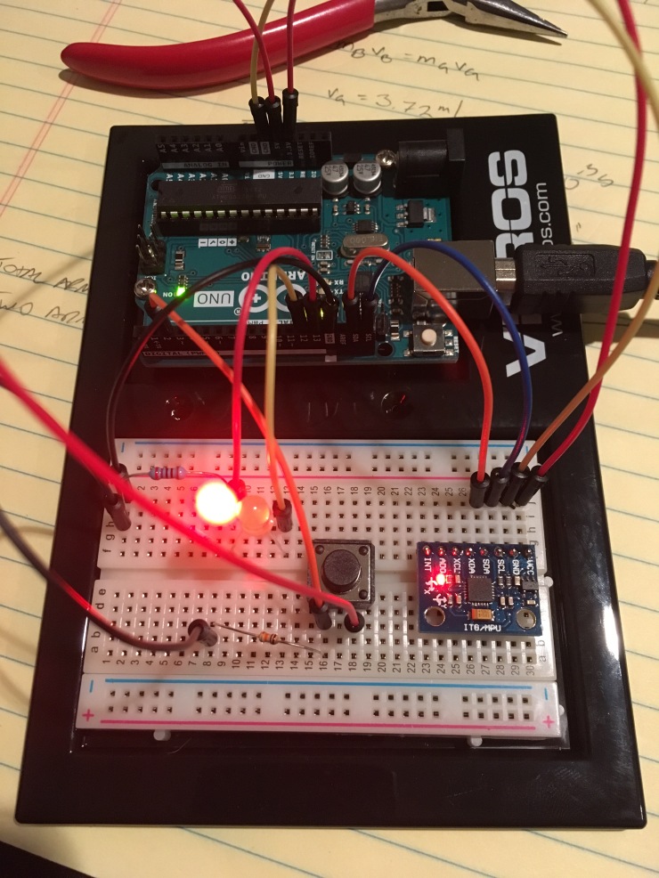
This is the complete setup with the button. You might notice that the circuitry around the button changed, I had to swap the way the toggle worked since using a high signal on PIN2 while the Audrino was crapping out massive amounts of data wasn’t a good idea since that caused PIN2 to drop to LOW logic and kept the cycle going on. Stopping, flipping, and reversing it like Missy Elliot did the trick and kept things nice and stable.
This is the code that I put together into a kind of Frankenstein abomination that totally got the job done! Let’s hope it doesn’t ask me to make another program that it can be weird with.
// Arduino Wire library is required if I2Cdev I2CDEV_ARDUINO_WIRE implementation
// is used in I2Cdev.h
#include "Wire.h"

// I2Cdev and MPU6050 must be installed as libraries, or else the .cpp/.h files
// for both classes must be in the include path of your project
#include "I2Cdev.h"
#include "MPU6050.h"

// class default I2C address is 0x68
// specific I2C addresses may be passed as a parameter here
// AD0 low = 0x68 (default for InvenSense evaluation board)
// AD0 high = 0x69
MPU6050 accelgyro;

int16_t ax, ay, az;
int16_t gx, gy, gz;

// constants won't change. They're used here to set pin numbers:
const int buttonPin = 2; // the number of the pushbutton pin
const int STOPPin = 13; // the number of the STOP LED pin
const int GOPin = 12; // the number of the GO LED pin
const long interval = 10000; // interval for how long the loop will run in miliseconds

// variables will change:
int buttonState = 0; // variable for reading the pushbutton status

void setup() {
   // join I2C bus (I2Cdev library doesn't do this automatically)
   Wire.begin();

   // initialize serial communication
   Serial.begin(38400);

   // initialize device
   Serial.println("Initializing I2C devices...");
   accelgyro.initialize();

   // verify connection
   Serial.println("Testing device connections...");
   Serial.println(accelgyro.testConnection() ? "MPU6050 connection successful" : "MPU6050 connection failed");

   // set acceleometer range
   accelgyro.setFullScaleAccelRange(2);

   // initialize the LED pins as an output:
   pinMode(GOPin, OUTPUT);
   pinMode(STOPPin, OUTPUT);
   // initialize the pushbutton pin as an input:
   pinMode(buttonPin, INPUT);
}

void loop() {
   // read the state of the pushbutton value:
   buttonState = digitalRead(buttonPin);

   if (buttonState == LOW) {
   // turn GO LED off:
   digitalWrite(GOPin, LOW);
   // turn STOP LED high:
   digitalWrite(STOPPin, HIGH);
   } else {

      unsigned long timenow = millis();
      unsigned long timethen = timenow;

      Serial.println("GO TIME! DUMPING DATA:");
      delay(1000);

      // turn STOP LED off:
      digitalWrite(STOPPin, LOW);
      // turn GO LED on:
      digitalWrite(GOPin, HIGH);

      while (timenow - timethen <= interval) {

         timenow = millis();

         // read raw accel/gyro measurements from device
         accelgyro.getMotion6(&ax, &ay, &az, &gx, &gy, &gz);

         // display tab-separated accel/gyro x/y/z values
         Serial.print("a/g:\t");
         Serial.print(ax); Serial.print("\t");
         Serial.print(ay); Serial.print("\t");
         Serial.print(az); Serial.print("\t");
         Serial.print(gx); Serial.print("\t");
         Serial.print(gy); Serial.print("\t");
         Serial.println(gz);
      }
   }
}
The following is a video of the serial output of the Arduino unit booting up, initializing, and the following deluge of data after I press the button to start the collection. You can see the values change as I maniacally tilt and twist the accelerometer.
OH! I also figured out what the numbers mean. The units are given in LSB/g for acceleration and LSB/(º/s) for the gyroscope. It basically means I need to divide whatever value it gives me by the LSB or “Least Significant Bit” which is given in the data sheet. In the previous example, the values were about 17200 for the z-axis, the least significant bit for that particular setting was 16,384 LSB. dividing 17200 by the LSB value I get how many g’s the sensor was detecting: Which was 1.05g’s. Perfect! There is a bit of error, but all sensors have a range of error.
In the data above, I’ve changed the sensitivity which also alters the LSB (for reasons which I’m not entirely sure of, I think it has to do with the bit representation of numbers), but doing so increases the range of values that it can detect. In the video, I’ve changed the sensitivity scale to increase the range of g’s it can read to ±8g’s which subsequently reduces its accuracy with the LSB to 4,096. With the LSB setting at 16,384, the range of values was only ±2g’s which wasn’t enough to cover the range of values needed for a gun firing (at least according to my preliminary calculations).
Okay, that’s it for today. I’m going to let my brain cool off while doing something else. Thanks for reading!
